Velox
DIY Electric Skateboard with 3D-Printed Motor Mount
summary_
In the last week of my time at the Massachusetts Institute of Technology (MIT), I saw someone seemingly floating as he zoomed past me, and it turned out he was on an electric skateboard he made himself. The desire to have one myself, coupled with some extra parts we were allowed to take back from my stint at MIT, eventually gave birth to Velox, the first DIY electric skateboard with a 3D-Printed motor mount on the Singapore University of Technology and Design (SUTD) campus.
Year 2014
Duration of Service 3
My Role Designer, Fabricator
Software SOLIDWORKS, CorelDRAW, MakerBot Desktop
Hardware MakerBot Replicator 2, Laser Cutter, Water Jet, Drill Press, Acrylic Bender, Screwdrivers Set, Soldering Kit
background_
After our eventful race, which was the finale for the Global Leadership Program I participated in, we immediately began packing up our electric go-karts and belongings in preparation for our flight back to Singapore. As we frantically disassembled our go-karts, our instructors told us that they had spare parts bought with the program’s fund that we could take home with us. They were limited in quantity, but I was fortunate enough to secure an Electronic Speed Controller (ESC) and a Brushless DC (BLDC) motor.
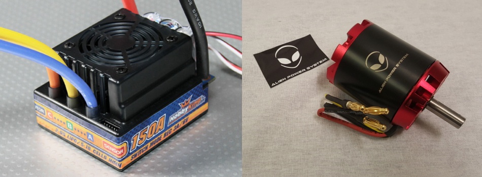
Having gotten these 2 parts further propelled my desire to build my own electric skateboard, having seen someone zoomed past me in one a couple of days back. Hence, right as we started our Sophomore Term, I kickstarted my electric skateboard building project, with the aim of making it compact and lightweight.
To design and build my own compact and lightweight electric skateboard
THE GOAL
research_
power and gear ratio calculation_
My plan was to use the two parts I had gotten for free as constraints to build the setup around. When I snagged both items, I was not sure whether they were both compatible. However, a quick Google search informed me that they were indeed compatible and that some actually used the same ESC for their own electric skateboard build.
As such, the remaining key items to get were the batteries and powertrain components. I decided to go with a timing pulley setup in favor of a chain setup because it’s more efficient and silent. However, the gear ratio between the motor and the wheel was yet to be decided.
In order to calculate the minimum gear ratio, I had to first find out the maximum torque generated by the motor, which in turn is dependent on the maximum current that could be handled by the batteries and ESC. The ESC I had gotten was rated for 150A burst current. However, it is generally a good practice to keep a minimum buffer of around 30%. Hence, the maximum current I could aim for was around 100A.
The batteries I aimed to use were lithium-polymer (LiPo) batteries, known for their high energy density, though it required more delicate care. The ESC I got was also rated for a maximum of 6 LiPo cells wired in series (6S). As each LiPo cell’s maximum voltage was 3.7V, a 6S setup would mean a maximum voltage of 22.2V. Whereas the current controls the maximum torque output by the motor, the voltage controls the maximum RPM of the motor. I decided to go with the maximum voltage allowable in order to attain the highest top speed possible.
With all these in mind, I came up with a simple calculation in Excel in order to estimate the ideal performance of my setup.
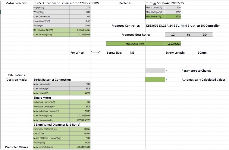
From the spreadsheet above, I could see that with the battery selection above and a gear ratio of 2.5:1, I should have sufficient torque for the motor to at least sustain the skateboard’s motion with a push start. At the same time, I would attain a maximum speed just shy of 30km/h, which was wild considering that I would be standing on a skateboard with no extra protection should I fell down.
mechanical considerations_
As I wanted to make this a compact and lightweight design, I decided to go with a skateboard instead of a full-size longboard. The initial rationale for making it compact and lightweight was for me to easily carry it on public transport. As such, this electric skateboard would serve as my last-mile transport.
However, choosing the form factor of a skateboard instead of a longboard came with its own set of problems, namely:
- Lack of space to house the electronics under the board, especially having to ensure that the motor would not hit the battery case when turning
- Lack of vertical clearance to ensure that the battery case and motor would not hit the ground when turning
- Skateboard wheels were too small to achieve the desired gear ratio
The last point could be solved by switching out those wheels with cruiser wheels instead, which were larger in diameter. However, this caused another huge problem: wheel bite. A wheel bite occurs when the board touches the wheel as the rider turns, causing the board to abruptly stop as the wheel’s rotation is suddenly halted. It is something all skateboarders avoid at all costs. As such, I had to get riser pads to elevate the board higher, which also helped in solving the second point above. However, manufacturers only produce riser pads up to a certain height as it reduces stability. Furthermore, the bolts holding them onto the board are only so long. Hence, I needed to find a sweet spot between the wheel diameter and the riser pad’s height.
In the end, I settled with the highest riser pad available in my local skateboard shop, which was 1/2″, and cruiser wheels with a maximum diameter of 70mm, which proved to solve the last two points without causing wheel bite. Procuring 2x3S batteries instead of 1x6S battery also helped with the second point.
However, in order to resolve the first point, I had to turn to computer-aided design (CAD) using SolidWorks.
parts design_
dimensioning and rough fitting_
By the time I started CAD-ing, I already had in my possession a skateboard I bought secondhand. Taking as close a measurement as I possibly could, I began designing the 3D model for the skateboard, motor, ESC, and batteries using either the physical items in my possession or online measurements.
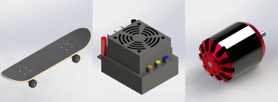
After CAD-ing these, I created an assembly file and place the components roughly on the board in order to size the possibility of fitting them all within the available space. Once they all seemed to fit, I procured the remaining parts before moving onto designing the mount for the motor.
motor mount design_
In keeping with my desire to keep the design lightweight as well as to circumvent the limited access I had to metal workshop on campus, I had decided to avoid the most common approach of creating the mount from sheet metal and welding it onto my trucks. This approach also helped in keeping my design modular and potentially one of a kind.
The first thing I did was dimensioning the distance between the axis of rotation of the wheel and that of the motor. To do this, I went to our local supplier to see the available timing belt lengths and having CAD-ed both the small and large pulleys, assembled both on SolidWorks in order to size the appropriate distance based on the timing belt’s lengths such that the latter would be tight when mounted yet the mount would not impede the skateboard’s turning.
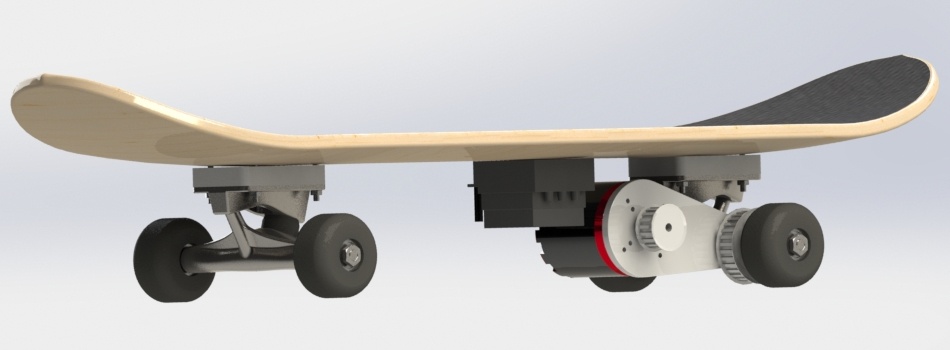
However, the sloped surface of the trucks meant that I had to find a way to somehow secure the mount to the trucks. The other common approach was to sand down the sloped surface until it was flat and then clamping down the mount onto the flat surface. However, I was not keen on permanently defacing the rear truck of my skateboard.
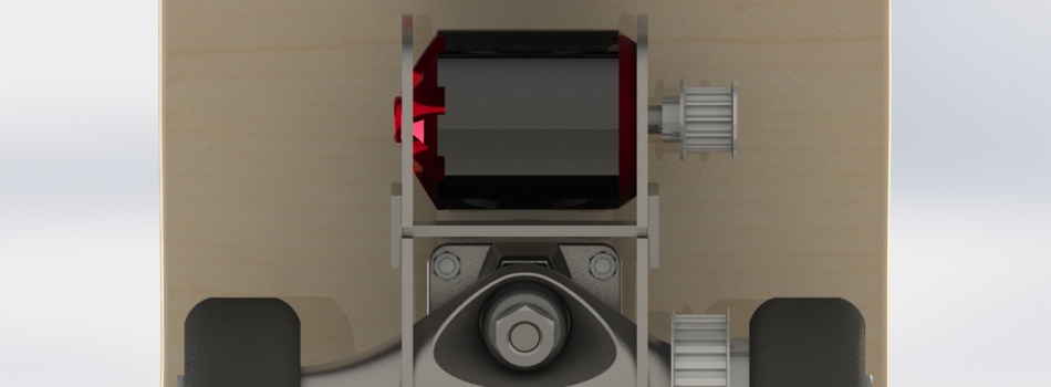
Having gotten blocked here, I decided to discuss this conundrum with some of my fellow course mates, and one of them came up with a brilliant idea of creating a nearly-identical piece to be connected from the other side of the truck with a few connecting pieces. This would ensure that the motor mount was mounted securely onto the truck, as shown in the CAD below.
fabrication and assembly_
Not wanting to use sheet metal for the motor mount in order to keep the build as light as possible, I first tried using a piece of plywood. I used laser cutting to produce the parts required. I also drilled the necessary holes onto the pulleys I bought, assisted by the campus’s metal lab supervisor.
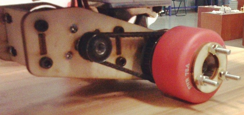
Once the preparation and fabrication were completed, I went ahead and mounted all the pieces onto my skateboard. There were a couple of hiccups at the start, mainly with the integrity of the motor mount design which required several iterations. Nonetheless, a few prototypes later and I finally got to the version below!
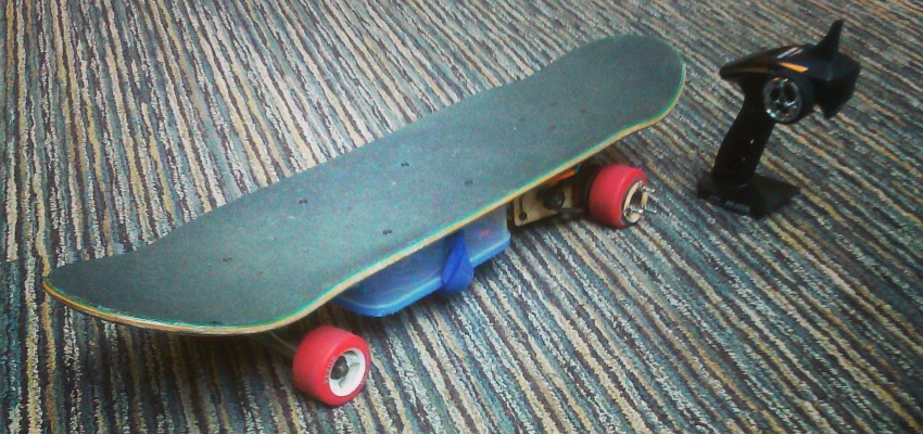
With the mechanical part assembled nicely, it was time to mount the electrical components onto the board. As I was on a budget, the container I used to house the batteries and ESC initially was a plastic lunch box! I simply drilled holes through it and the skateboard. Then I used screws to mount the lunch box onto the board, before putting all the components inside. Initially, the plastic lid easily gave away at the slightest bump, spewing all the contents out of the box. To mitigate this, I slid a velcro tape in between the board and the lunch box and used it to further secure the lid.
And with that, the first version of Velox was completed!
test drives and improvements_
The insecure lid issue above was actually found out during one of my early test drives. In fact, I considered every ride with Velox to be a test drive, as some problems only became apparent with time and frequent usage. Admittedly, there were plenty of issues I found throughout the years Velox was in service, and some were not properly addressed until much later. They were as follows:
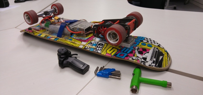
- The lunch box which housed the electronics was too thick, resulting in really low ground clearance. Whereas the turning was not affected, I was not able to go even the gentlest of speed bumps, which were common in Singapore. The first thing I did to resolve this was to bend my own containers using acrylic. I also decided to remove the fan from the ESC, relying instead on the wind to blow the heat away. This solution got me to the slimmest and sleekest version of Velox, but it came at the cost of much poorer water insulation. I stuck by it until 2017 when someone who also built his own electric skateboard informed me of a place to get an affordable waterproof electrical box, which ended up being the permanent solution to this conundrum.
- The large pulley which was mounted on one of the rear wheels initially had the 3 screw holes drilled manually using a bench press. As much as I tried to mark the points accurately in order to ensure that the pulley will be centered on the rotating axis, it turned out off-centered when I mounted it. As such, I eventually decided to water jet my own large pulley using an aluminum sheet. This resulted in a perfectly centered pulley which drove the skateboard much better, even though the lack of proper finishing after the water jet had a slight adverse effect on the drivetrain’s efficiency. I also replaced the small pulley with a new one that was drilled in a more centered manner than the previous one.
- I also made changes with the circuitry as time progressed. The first modification I made was adding LED strips that could be turned on and off with my controller. That then got decommissioned when I swapped out the bulky HobbyKing controller with a smaller version, and when I introduced the proper waterproof housing I wired in a 3-step mechanical battery indicator based on Zener diodes.
- Constant usage would cause the timing belt to stretch. As the initial mount design had fixed holes for the motor, this would cause reduced tension and torque, as the timing belt would frequently jump. To alleviate this issue, as well as the need to precisely calibrate the distance between the two pulleys, I swapped out the fixed holes with slots that would allow me to slide the motor closer or further from the wheel. It even enabled me to swap worn out belt with a new one without having to disassemble the whole drivetrain.
- Wood turned out to be too brittle. Frequent bumps would cause the motor mount to develop cracks, either near where the motor was mounted or where the mount was attached to the truck. One of my course mates suggested trying out 3D-printed material, which turned out much better as it was malleable instead of brittle. At 100% filling and relying on plastic deformation to increase the strength of the material where the mount met the truck, this version of the motor mount never developed cracks. However, frequent riding on uneven terrain would cause the hole where the truck handle fitted to grow bigger. Eventually, it would get so lose that the motor would move up and down. The geometry of this motion resulted in uneven tensioning of the timing belt, thus reducing its torque. I found myself having to reprint a new mount every 3-4 months. It was only in 2017, when I no longer had access to a 3D printer, that I went ahead with an all-metal setup for increased longevity.
- As a bonus, I got myself a smaller hand throttle as well 🙂
evaluation_
Given how little I knew about mechatronics prior to the go-kart project and Velox, I was really delighted with how well the later functioned throughout my time in SUTD. It was practically my go-to means of transport from my dorm room to my classes, as well as in between classes! There were also plenty of times when I brought Velox out to skate-friendly places such as the Marina Bay Sands. The continuous improvements had also been nothing but a valuable learning experience, not just technically but also on the importance of continuous iteration.

Being the first electric skateboard to roam around SUTD, and possibly the first-ever with a 3D-printed motor mount, Velox was featured in various SUTD Open Houses, specifically inside the SUTD Library as an exhibit. It also inspired several others to build their own versions on campus. Unfortunately, in 2017 Singapore came up with a much stricter law governing Personal Mobility Devices (PMDs), which ruled out the usage of Velox in public. However, I was fortunate enough to get this footage shot right in front of the ArtScience Museum before the rule kicked in!

