ZOUBA
Last-Mile Transportation that Fits into Your Bag
summary_
ZOUBA was the product of our attempt at designing the perfect urban last-mile transportation in collaboration with Gilmour Space Technologies. Three-wheeled for stability yet portable enough to fit into your backpack, ZOUBA was designed to make the short trips between public transit to your destination faster, safer, and more fun.
Year 2016
Team Stevanus Satria, Lee Jia Wen, Chen Yiliang Brandon, Nguyen Van Duong (Harry), Terence Tay Yong Xing
My Role Designer, Fabricator
Software SOLIDWORKS, CorelDRAW, MakerBot Desktop
Hardware MakerBot Replicator 2, Laser Cutter, Water Jet, Drill Press, Screwdrivers Set, Soldering Kit
background_
With 4.43 million daily commutes spanning across more than 200 buses and train lines, Singapore’s public transport system stands as one of the best in the world. Whereas the current ecosystem is efficient and reliable, transiting between the personal means of transport, such as walking, and the public transport network still proves to be cumbersome.
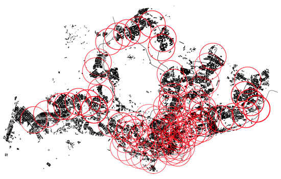
Looking at the map above, in which circles with radii of 2km were drawn around each Mass Rapid Transit (MRT) stations, a problem became apparent. 2km is considered the maximum walkable distance for regular commute. Whereas the distance between an MRT station to the next is most less than 2km in areas closer to the city center, in some areas further away the distance was greater. For some stations the circles did not even overlap, which meant a distance of more than 4km between them. Admittedly, there would be bus services to connect housing estates to the nearest MRT station but in some cases these buses were infrequent and crowded during peak hours.
Dubbed as the ‘last mile problem’, none of the currently marketed products fully resolved this issue, despite them being marketed as ‘last mile solutions’. Therefore, Team ZOUBA identifies the tacit need to provide the ideal linkage between the two realms of transport; one that is simple, lightweight, and portable without compromising on its versatility and performance. The product must also be affordable to boost its accessibility to the masses.
To design and fabricate a last-mile transportation that is simple, lightweight, affordable, and portable without compromising on its versatility and performance
THE GOAL
research_
the “SEED” diagram and “TRILO”_
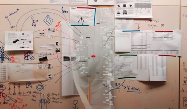
The SEED Diagram shown above was our interpretation of Bruno Latour’s Actor-Network Diagram. By mapping the various facades of a PEV and assigning existing examples of each, we were able to pinpoint the advantages and disadvantages of each design. Subsequently, we filtered out the desirable traits and assign them as design requirements for the product. After various iterations and 3 promising designs, we eventually decided on the unique foldable concept named “TRILO”.
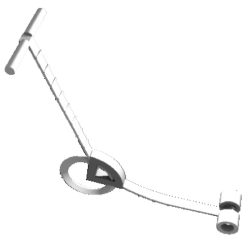
evolution of “TRILO”_
After various attempts to compact the design, the limiting factor was discovered to be that of the back wheels which contained the motors. Due to this, the form was designed around this constraint whilst implementing the above concept of having a segmented body.
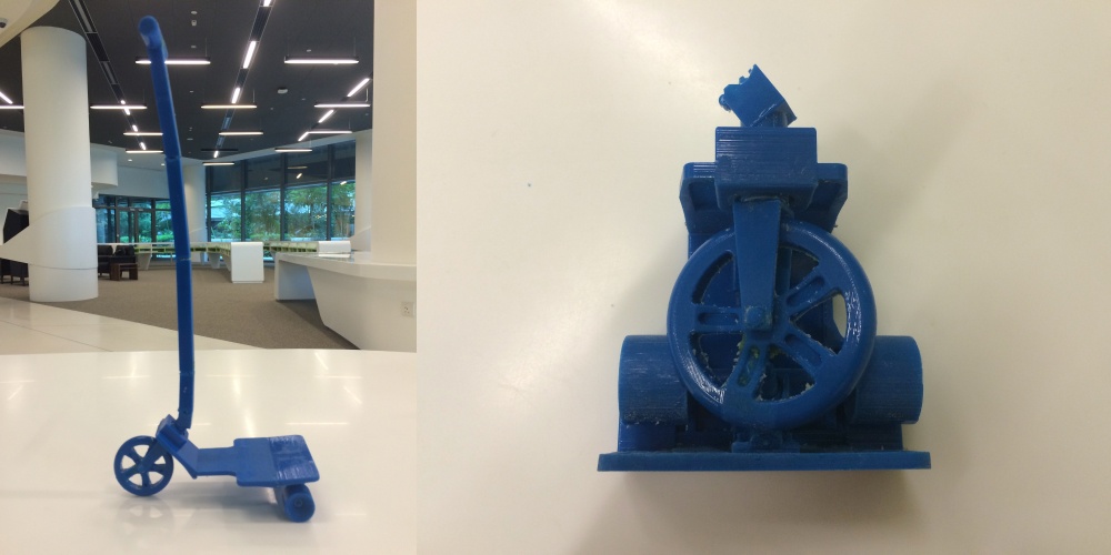
The above folding and compacted form were derived after various attempts to optimize the volume of space it will occupy. The above miniature prototype allowed us to understand how the whole form would fold and what it would eventually look like after folding.
base platform design_
Once we finalized the form factor of the solution, I was assigned the role of designing the base platform of the vehicle.
dimension exploration_
The development of the chassis or frame of ZOUBA was conducted in tandem with that of the handle. Just as it was imperative for the handle to exhibit some form of transformation, the frame must be able to expand and collapse in order to increase or decrease ZOUBA’s footprint as necessitated by its usage. Hence, the exploration for the base platform revolved mainly on (a) the dimensioning of the expanded and collapsed form, (b) the transformation mechanism that provides the necessary transformation without compromising on structural integrity, and (c) geometrical reinforcements of the frame to optimize the strength-to-weight ratio.
full-scale wooden prototypes_
The first step I took was to determine the appropriate dimensioning for the board. I started by trying to wrap the base platform around the larger front wheel. However, I soon realized that primary limitation when it came to collapsing the deployed base platform into a more compact form was the two protruding rear wheels. Hence, I decided to try folding the frame around the rear wheels instead. In order to optimize the dimensions when folded, I made sure that the front wheel tucks inwards to form the last side of a cube, i.e. the front wheel itself is the final side of a 4-sided cuboid.
Using plywood, which was cheap and readily available, I quickly machined a rough full-scale low-fidelity prototype out. Three separate pieces were produced, all of which were joined together using several small door hinges. All of these were done using common workshop tools such as band saw, drill press, and belt sander. The end product was the smallest base platform ever built, dimensioned to be around the size of a 13” laptop when unfolded.
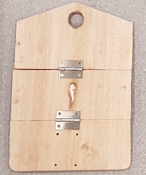
The abovementioned frame was measured to be 360mm by 250mm by 8mm when unfolded, whereas it was 122mm by 250mm by 160mm when folded. It was too narrow for a person to stand on, and the distance from the handle to the rider’s chest was too near for comfort. Nevertheless, given a person’s ability to stand on it and steer, I decided to set this frame as the lower dimensional limit for the ZOUBA base platform.
With the lower limit determined, I went on to determine the upper limit of the frame’s dimension, this time dimensioning the frame according to a 17” laptop when folded. Still using plywood, and applying similar manufacturing techniques, the second full-scale low-fidelity prototype was produced.
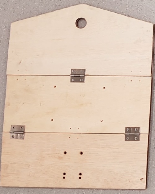
The abovementioned frame was measured to be 487 mm by 380 mm by 8 mm when unfolded, whereas it was 177 mm by 380 mm by 202 mm when folded. I tested the comfort level by trying the fully assembled prototype myself! Indeed, it was more comfortable to stand on, but the above dimensions were too large to fit comfortably into a typical backpack. Nevertheless, upon discussing with the others, we decided to keep these dimensions as the upper limit owing to the much-improved comfort when used.
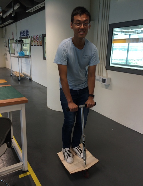
Furthermore, whereas the small hinges did not give way during the static test (partly due to more of them being used), the screw holes where the hinges were mounted became larger due to the 25 stress concentration resulting from the interface between two different materials (wood and metal screws). I thus learned that wood was not an ideal material to use for this product, because unlike unibody personal vehicles such as skateboards and longboards, a strong folding mechanism was required. Such mechanism tends to be made out of metal, and thus I decided to move away from wooden designs into metal-based designs.
full-scale metal prototypes_
Aluminum and its alloys have always stood out as favorites when designing products that require both strength and being lightweight. Thus, for the first full-scale metal-based prototype, I decided to try using 6061 aluminum alloy as the base material. I also decided that since the end-to-end distance between the rear wheels was 270 mm, the same measurement would be used as the width of base platform.
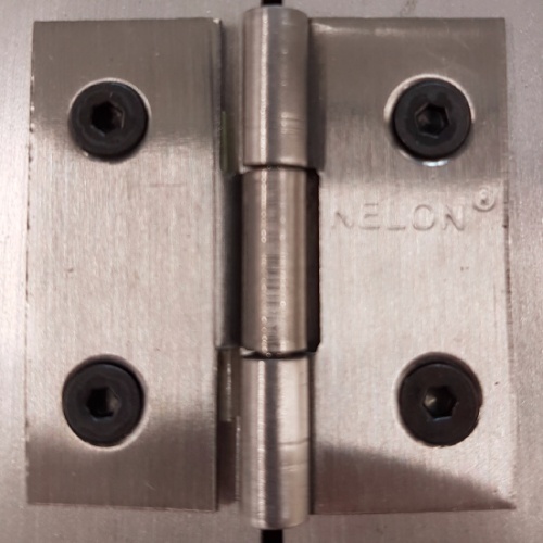
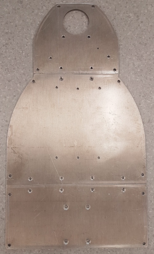
The first prototype was manufactured from a 5mm-thick 6061 sheet using an advanced water jet machine. The holes for the hinges were pre-assigned beforehand to ensure a greater precision, which would, in turn, guarantee the flatness of the frame when unfolded. The hinges were then assembled onto the jetted plates, and instead of using screws, I substituted them with M3 bolts and nuts.
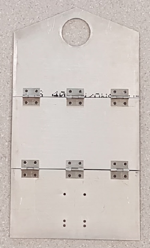
The abovementioned frame was measured to be 487 mm by 270 mm by 5mm when unfolded, whereas it was 169mm by 270mm by 202mm when folded. It was indeed nearly 3 times as heavy as its wooden counterpart. The pre-assigned holes ensured that the plates were parallel with one another when unfolded, and the overall feel of the prototype was amazing.
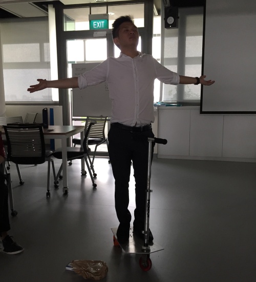
We went on to conduct both static and dynamic stress tests on this prototype, and the outcome exceeded our expectations. Each member was able to comfortably ride the product around, and the smaller hinges withstood the various loads (55-75kg) quite well. They did, nevertheless, give way slightly, as shown in the Figure above where the plates were no longer parallel when loaded. This was made even apparent when a 100kg person stood on the frame. Upon inspecting the frame afterward, we discovered that the bending was due to the small hinges being stretched plastically beyond its designed length.
final dimensions_
Considering all the iterations performed previously, we decided on a deployed length of 476mm and width of 270mm, whereas when folded the volumetric dimension should be within 175mm by 262mm by 270mm. The thickness of the deployed length was yet to be determined as this depends on the material selection and structural reinforcements applied to the design. Nonetheless, these were the dimensions that we believed would optimize the stability and comfort of the rider without compromising on the product’s portability.
Given the takeaways from the previous prototypes, we embarked on resolving 3 major design challenges with regards to the product’s frame, namely:
- Applying the appropriate reinforcement methods to allow for a lighter frame without compromising on both strength and stiffness.
- Determining the most suitable material for the base platform that is stiff, strong, and lightweight.
- Determining the most appropriate method of folding that retains the rigidity and strength of the base platform.
materials exploration_
On top of designing the form factor of the base platform, I also had to source the most suitable material to fabricate it with. We had already planned on having the rudimentary design above supported by trusses, and our teammate who’s background was architecture helped us come up with the best geometric pattern for the trusses.
I conducted this material exploration through 3 phases: (a) preliminary shortlist using the CES Edupack, (b) consultation with material scientist, and (c) perform simulations for all remaining shortlists.
preliminary shortlist_
The first phase was performed by filtering materials based on our desired properties as well as the material index. For this product, the selected material must have excellent stiffness and yield strength, as well as sufficient weather resistance. I went on to perform a logarithmic plot between Yield Strength against Density. The gradient of the line plotted was 2, based on the formula mentioned. This helped me filter the material with the best strength-to-weight ratio out of the plethora of selections available.
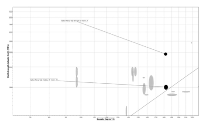
As seen from the graph above, the only material that optimized the above two Limits is carbon fiber. Specifically, there are two types that are most suitable for the frame: High Strength or High Modulus Carbon Fibers (5 microns, f). Given that the average price of the High Strength Type is S$40/kg, it is plausible to use this material to fabricate the vehicle’s base platform given our targeted frame weight of 1.5kg.
consultation with material scientist_
Upon consultation with Prof. Tan Mei Chee, who was a material scientist, I learned that unique to our design, carbon fibers were not viable. This was due to the fact that the 32 loading in between two plates of the frame was compressive in nature, whereas carbon fibers are meant for tensile stress. Thus, Prof. Tan proposed 3 alternatives to us: (a) epoxy/fiberglass composite, (b) phenolic/fiberglass composite, and (c) nylon. Given the lack of personal protective equipment to deal with making composites, I decided to shortlist nylon as an alternative to aluminum for the frame’s base material.
simulation_
With the support of the National Additive Manufacturing Innovation Cluster (NAMIC), we were able to secure a means of prototyping a nylon-based frame for the product. However, given the high cost of industry-grade additive manufacturing, we were allowed a maximum of 2 full-scale prints. Hence, Mr. Teoh You Jian from NAMIC encouraged us to perform Finite Element Analysis (FEA) considering the worst-case loading on the product’s frame before proceeding with the prints.
Having created the base platform’s CAD with trusses added, Brandon helped perform the FEA using SolidWorks Simulations. The rider of the product was simulated as forces uniformly distributed on the left and right one-third of the back and mid plates. The backplate was fixed to the ground, whereas the front wheel was allowed to roll on the ground. Given that this simulation was more akin to a static loading than a dynamic loading, a safety factor of 2 for a 100kg person was desired. Hence, the total force exerted on the product was assigned to be 2000N. The results of the FEA is as follows:
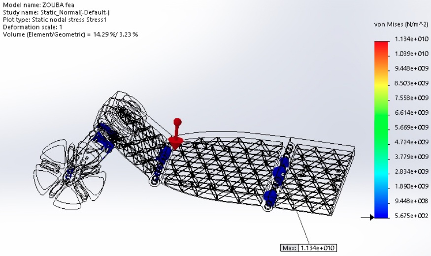
With regards to the regions of stress concentration, the area of highest stress concentration lied at the front half of the vehicle, which was expected due to the rider standing closer to the rear of the product. Three of the most stressed areas were (a) the steering column, (b) the inner core of the front hinge, and (c) the inner core of the rear hinge. Whereas (a) was not part of our utmost concern as it was fabricated using aluminum, we were unable to ensure the structural integrity of (b) and (c), despite inserting a metal bushing in between the steel rod and the plastic slot. We still printed a mock-up of what could have been had the nylon design worked, but ultimately it was decided that the best material to utilize for this product was aluminum.
folding mechanism_
Lastly, to complete the whole design of the base platform, I had to source a suitable folding mechanism for it.
The first decision to be made with regards to the folding mechanism was whether it would be advantageous to hybridize the primary hinge folding mechanism with other mechanisms. Upon extensive deliberation, I decided not to proceed with this idea as additional mechanism variation would mean increased complexity which would make the product less user friendly. In fact, I decided to keep the number of mechanisms to a minimum to allow for quick folding and deployment of the product.
Thus, the choice was to keep the existing hinge folding mechanisms. Given the structural failure of the small hinges used previously, as well as the failure of the polymeric integrated hinge design, I embarked instead on a quest to find the most suitable hinge for the frame; those that were lightweight yet strong and durable.
I learned that the stress distribution of a typical hinge is concentrated on the metal pin, as well as the edges of each barrel. Thus, it was imperative that the selected hinge has a large enough metal pin as well as a sufficient number of barrels. Thus the need to optimize between the improved strength of a larger, longer hinge, and the increased weight that came with it. It was determined that a longer hinge was preferred compared to a thicker pin, as the latter would increase the bulk of the form factor as well. Hence, I decided to source for hinges that 34 spanned a close to the width of the frame as possible. The rear hinge must therefore span as close to 270mm as possible, whereas the front hinge must span as close to 166mm as possible.
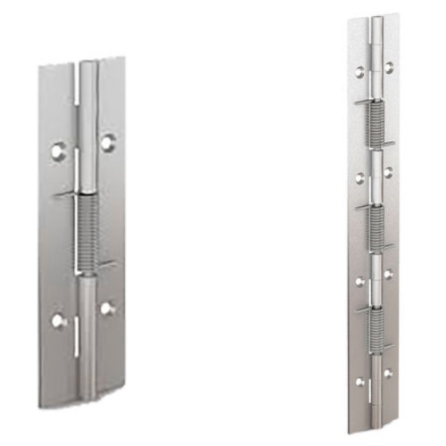
Spring-Loaded 120mm (left) and 240mm (right) Hinges (© Pinet)
After sourcing through the available local suppliers, I selected two Pinet spring-loaded hinges. The smaller 120mm version was chosen for the front connection, whereas the larger 240mm was for the rear connection. Both hinges were loaded to be self-opening, which would facilitate a one-step deployment of the product. Tests on both hinges were performed when I assembled the first full integration of the product.
fabrication and assembly_
mechanical integration_
The first integration was assembled on the final form factor mock-up, which was fabricated using 5mm-thick 6061 alloy. The whole assembly comprised all the sourced parts previously mentioned or fabricated, with the exception of the electronics. The handle, meanwhile, was prototyped using 8020 aluminum extrusions.
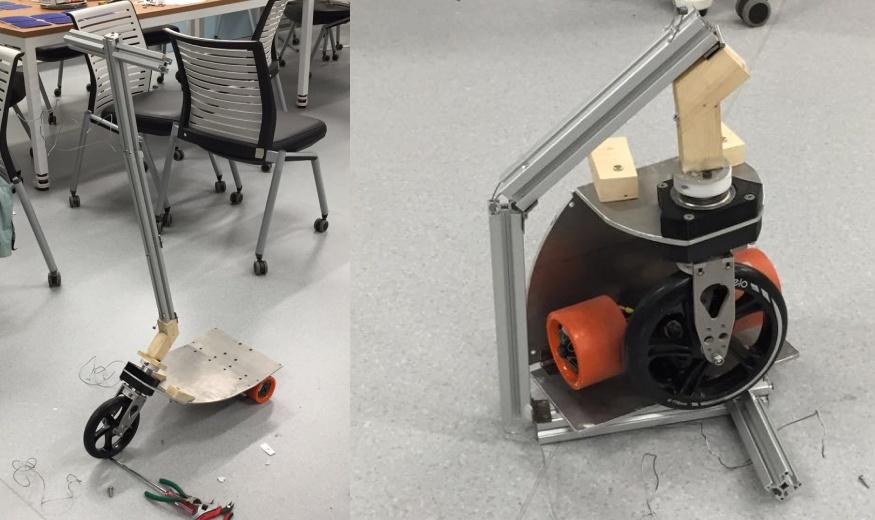
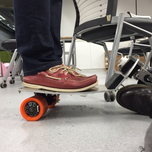
The initial assembly of this integration did not include the front wooden support shown above. This support was added in when excessive flexing occurred the moment someone stood on the entire product, which improved the stress distribution between the front plate and mid-plate. However, the overall integration was much heavier than ideal, which led to our attempt at integrating the ribs into the frame of the product.
reducing weight_
We then tried the same form factor made out of a solid 3mm-thick 6061 alloy reinforced with 3mm-thick triangular ribs. This was primarily aimed at retaining not only the form factor of the previous iteration as much as possible, but also to significantly reduce the weight of this iteration. Furthermore, the first full integration was the version where the electronics bay was mounted and tested for the first time.
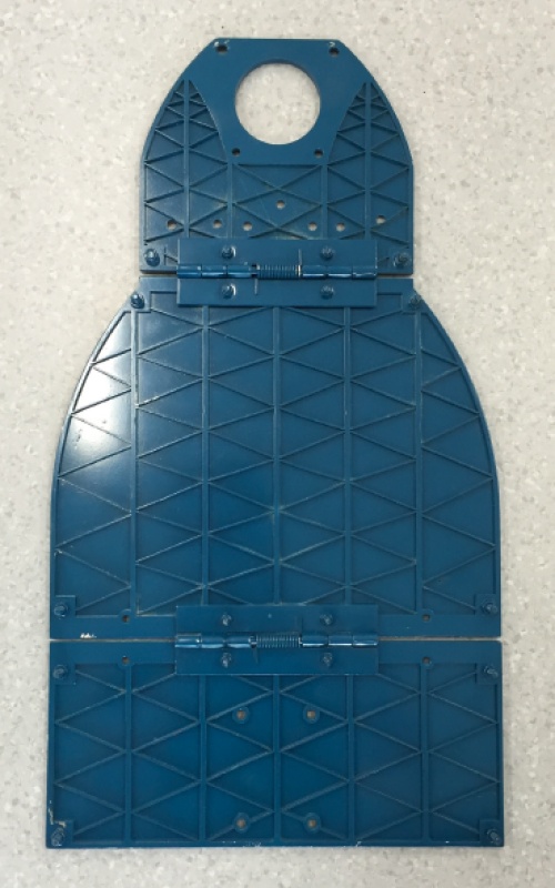
The above frame, weighing a mere 1.3kg, was the lightest frame ever produced by us. When assembled, the overall product was also able to fold and unfold as intended. However, being the lightest frame ever put together might not necessarily be the best solution for this platform. A large amount of deflection was noticed when the user applied weight on the structural platform, causing a safety concern in the driving performance. Through analysis, it was discovered that ribs weren’t sufficiently thick to support and withstand the load applied by the user. In fact, the ribs were extremely thin (a mere 1mm) that one can break them with the push of a finger. Furthermore, the front bearing housings fractured after several rounds of testing due to insufficient material surrounding the bolt holes. As discovered upon closer inspection, two of the bolt holes were designed too near the edge of the housings.
full integration_
The first full integration showed that a redesign to the current structural platform was necessary. The 3mm solid structural plate remains, as it is proven to be strong enough, but the ribs were redesigned and reinforced with a 5mm thick material. The ribs themselves were made thicker (by 2mm instead of 1mm). As such at a weight of 1.6kg, the frame is now 300g heavier to the previous version.
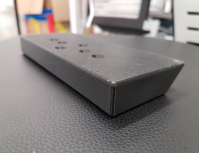
The wooden support implemented in the previous integration was also improved. Instead of 2 pieces of wood, we proceeded with manufacturing a longer single piece support using additive manufacturing technology. This had helped us in ensuring the accuracy of the angle of the support, ensuring excellent contact between the support and the mid-plate.
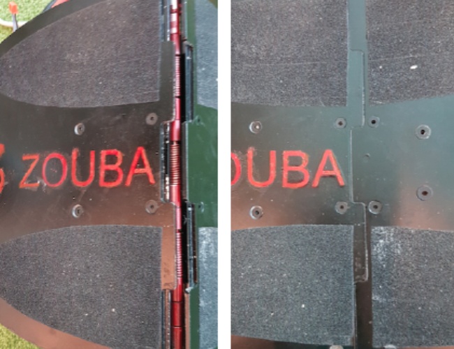
Another innovation we made to the overall frame were overlapping “fingers” between the mid and rear plates. Similar to the above-mentioned support, it was designed to improve the stress distribution between the mid and rear plates. Instead of relying on the minimum surface area between two plates, we designed these “fingers” to ensure that the rear plate was in contact with the mid ribs, and vice versa.
evaluation_
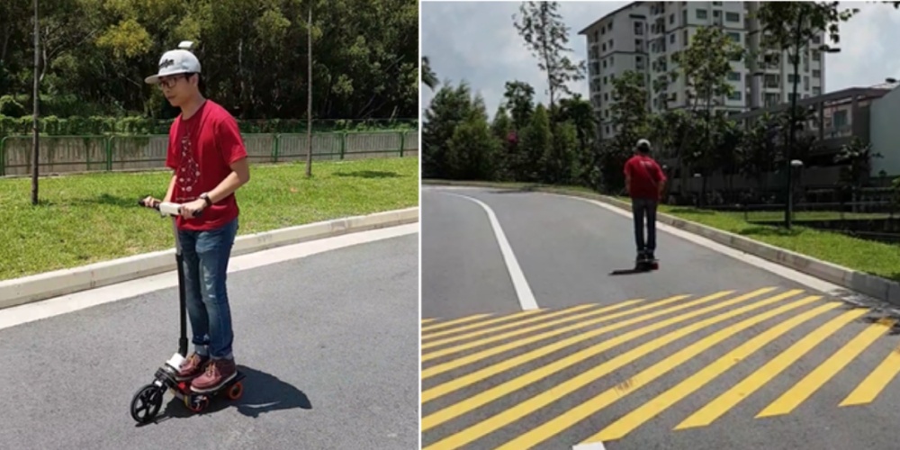
We were extremely delighted and proud of what we achieved in ZOUBA! It ended up being ergonomically ideal last-mile transportation for riders of around 60kg and 1.65m. It had sufficient acceleration, excellent top speed, and was capable of going up gentle slopes. The 3-wheeled design and handle also made it a much more stable alternative compared to a scooter or skateboard. Most importantly, it was portable, lightweight, and safe for everyone to use 🙂


