SALAMANDER
Portable Amphibious Spherical Rolling Robot with Live-Streaming Capability
summary_
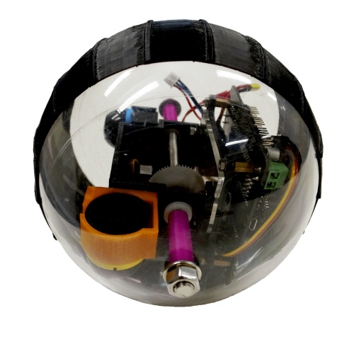
SALAMANDER was a reimagination of what a rolling robot could do. It was born from a project where we were tasked to modify an existing kart-in-a-wheel rolling robot design by adding a key differentiating factor. Over the course of a whole semester, we researched and redesigned the robot into one specialized in surveillance and reconnaissance while still being lightweight and portable. The end result was a 2-axis pendulum mechanism with 2 live-stream capable cameras mounted inside a spherical shell insulated with a 3D-printed sleeve.
Year 2015
Team Stevanus Satria, Lee Jia Wen, Chan Wei Ting Samantha
My Role Designer, Fabricator
Software SOLIDWORKS, CorelDRAW, MakerBot Desktop
Hardware MakerBot Replicator 2, Laser Cutter, Water Jet, Drill Press, CNC Lathe, Screwdrivers Set, Soldering Kit
background_
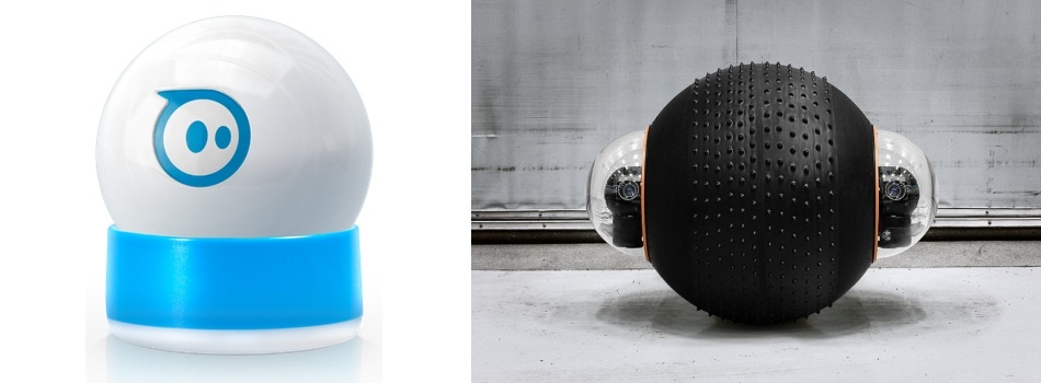
Spherical rolling robots were proving to be versatile robots. Whereas Sphero made use of this design to make toys, Rotundus turned it into a surveillance robot. The potential advantages of a rolling robot design vary from being omnidirectional to being potentially orientation-independent. This was why even in the Singapore University of Technology and Design (SUTD), a group of researchers was collaborating with Singapore’s Ministry of Defense in order to explore the possibility of deploying miniature rolling robots on the battlefield.
The professors decided to bring this concept to class during our 30.007 Engineering Design and Project Engineering course. The task was simple: redesign a simple kart-in-a-wheel spherical rolling robot within a budget of S$500 and add a key differentiating feature into it.
One of the things we noticed right away about the kart-in-a-wheel design was that it was not fully orientation independent. There was an off-chance the kart inside the sphere may flip, rendering the robot immobile. Hence, we decided to make our design orientation independent.
The other thing that we wanted to add was waterproofing in order to make the robot more robust to changes in terrain and weather. However, as we discussed more, we realized that an interesting concept to explore would be to make a robot that can roll both on water and the ground. Thus we decided that we would not only make the robot waterproof but also amphibious.
To redesign an orientation independent, waterproof, and amphibious spherical rolling robot within a budget constraint
THE GOAL
research_
The first thing we looked into redesign was the drivetrain design of the rolling robot. We brainstormed various possibilities and shortlisted them into 3 most promising ones: geared wheels and steering pendulum, 2-axis pendulum, and 4 Omni wheels. From here on, we came up with a Pugh Chart in order to objectively weigh the pros and cons of each design.
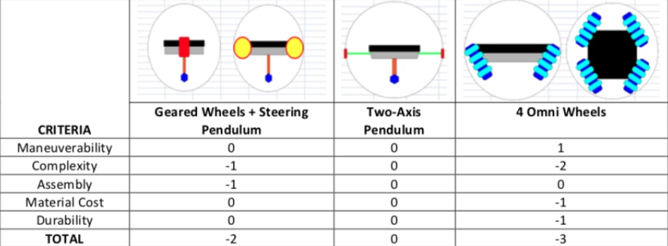
Taking the 2-axis pendulum as the datum, we realized that the other two designs were not only more complex, but the gains provided were not significant compared to the datum. As such, we decided to go with the 2-axis pendulum as our drivetrain design.
With the drivetrain set, we immediately went ahead towards figuring out a way to waterproof the whole design. The shell of our robot comprised two halves that mated nicely in the middle, which resulted in the first most apparent gap. Given our choice of drivetrain, there would be 2 more places water could leak into the robot’s internals, namely the two ends where the central pendulum axis would be bolted on.
As such, in order to achieve our waterproofing, we needed to ensure water could not enter through these 3 areas. After brainstorming for quite some time, we decided to try out rubber gaskets for the 2 contact points of the central pendulum axis, and a unique elastic 3D-printed sleeve for the gap where the 2 halves met.
From here on, we decided to split the sub-tasks amongst ourselves, and I was entrusted with designing the 2-axis pendulum drivetrain of the robot.
parts design_
first iteration_
As we were given an actual working kart-in-a-wheel spherical rolling robot, we tried to reuse as much of the parts available as possible in order to save up on our budget. Unfortunately, the kart within the spherical shell was driven using a differential drive system. As the kart was able to turn based on the difference in the left and right wheels’ RPM, no servo was needed to tilt the wheels. Hence the only things we could reuse were the Pololu Microgear Motor, the spur gear connected to it, the DFRobot Romeo V2 microcontroller, battery, Bluetooth module, and external spherical shell.
In order to try to optimize the limited space within the spherical shell as much as possible, the original plan I came up with was to have the microcontroller and battery act as the secondary pendulum used for turning, instead of creating a dedicated deadweight. This was in line with our desire to keep the weight to a minimum as we needed to ensure the robot floated on the water. This would be connected to a servo, which would be mounted on a 3D-printed case which also housed 2 live-streaming cameras we managed to fit into the budget and the Pololu motor. The main shaft would then be put through both halves of the shell, and a spur gear would bite into that of the Pololu motor. The gear ratio chosen was 3:1 in order to ensure that the small motor produced enough torque to start rotating the pendulum around the main shaft.
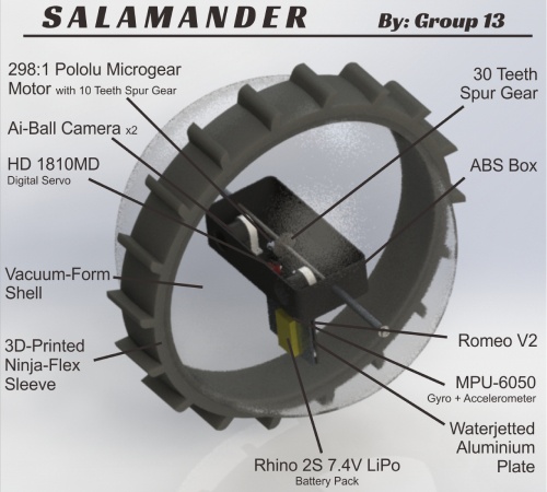
Now, one might wonder how this would move the shell forward, as the shaft would simply rotate about the shell instead of the shell rolling. To answer this question, I proposed putting a rubber gasket and a washer before fastening the nut on either side of the main shaft. The idea was to have the washer push tightly against the rubber gasket. This would hopefully result in 2 things: (a) that enough friction existed between the shaft and the shell such that the moment from the pendulum causes the shell to roll forward and (b) the gaskets would prevent water from entering the shell. Talk about (hopefully) killing two birds with one stone!
prototyping and modifications_
We decided to quickly prototype the sleeve above for two reasons: (a) we needed to make sure it’s waterproof enough and (b) the cameras’ position would change should there be a need to widen its design. The original reason we designed it that thin was to make it easier to slip onto the shell and provide more transparent surface area for the cameras. However, the moment we tried the submersion test we realized that the sleeve was too thin to seal the whole shell. We also noticed a problem with the robot on the ground; because the sleeve was too thin, when the robot tilted (which would happen when it turns), the shell got into contact with the ground instead of the sleeve, and the difference in thickness meant the robot found it much harder to return back to its erect position.
At the same time, when discussing the mechanical design with our professors, they were against the idea of swinging the microcontroller and battery as deadweight as doing so would risk disconnecting some of the wirings on the microcontroller. In addition, should we wish to connect more sensors for the robot, having the microcontroller stationary relative to the main pendulum body would make things simpler.
I went ahead with redesigning the robot’s drivetrain in order to incorporate all the learnings above. Firstly, instead of having the cameras mounted inside, I decided to have them mounted outside of the container. This would not only make assembling/disassembling easier but allow me to mount the cameras further out to the sides, thus giving my teammate, Samantha, greater flexibility when redesigning the outer sleeve. I also mounted the first camera facing forward and the second facing downward in order to add more viewing angles. In this new design, the Romeo V2 microcontroller would be mounted at the back of the container.
In exchange, a set of aluminum sheets would be used as deadweights for the secondary pendulum. I decided on using stackable sheets instead of machining a single slab because it allowed for greater flexibility when it came to tuning the pendulum’s and robot’s weights. The stack of aluminum sheets would be fabricated using a water jet and secured to each other with a set of bolts and nuts.
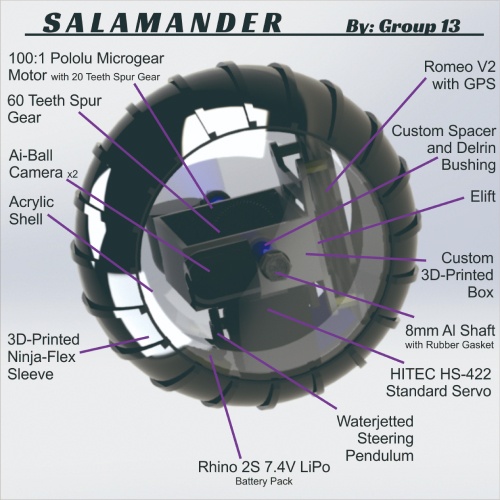
As you can see from the rendering above, I also added 3D-printed spacers in order or keep the pendulum from shifting left and right. I also added a Delrin bushing to allow the container to rotate more smoothly around the main shaft. The reason I went ahead with Delrin bushing instead of a ball bearing was to keep the weight at a minimum.
In order to make sure the designs would work before moving ahead with the high-fidelity functional prototype, I decided to laser cut the secondary pendulum sheets in order to test the dimensions. Thankfully, I managed to catch and fix the excessive height issue in this phase, and prevented myself from having to water jet the sheets twice!
Samantha was also able to nail the thickness and printing parameters of the NinjaFlex material on the MakerBot Replicator 2 such that the sleeve came out elastic enough to be put on but snug enough to waterproof the whole robot. With all these, we were ready to fabricate the first working SALAMANDER.
fabrication and assembly_
Some of the finalized parts from the low-fidelity prototypes, such as the main container and 3D-printed outer sleeve, could be reused, and so we did. The others, like the secondary pendulum weight sheets and Delrin bushings, had to be fabricated properly with the correct materials.
Once the preparation and fabrication were completed, we simply assembled everything in place. It was a relatively simple process, thanks to our attention to detail during the low-fidelity prototyping phase. Within an hour of assembling, SALAMANDER was completed!
wrapping up_
programming_
Since we got ourselves a Bluetooth module with the original kart-in-wheel design, we decided to preserve the Bluetooth control functionality and modified the included basic mobile application to suit our needs. Both Samantha and Jaron (Jia Wen) handled the mobile application and Arduino sketch modifications respectively, and after a couple of hours of coding and debugging they were able to make SALAMANDER fully controllable via an Android phone.
systems modeling_
After the initial module that SALAMANDER was built for, we took it a step further and converted it into a research endeavor under the Undergraduate Research Opportunities Program (UROP). It was during this phase that I modeled out the entire system. The idea was to then design a systems controller in order to improve the robot’s locomotion, such as reducing oscillations before and after motions as well as during turns. However, we only managed to get up to the stage of drafting the dynamic model and approximating it to a 2nd order differential equation.
evaluation_
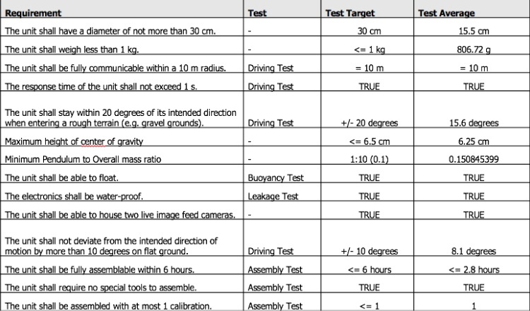
We were really happy with how SALAMANDER turned out! Not only did it meet nearly everything that we set out to achieve (bar the ability to escape a pothole and having a swivel mechanism for one of the cameras), but it was one of the robots that caught the interest of many people during the exhibition. It was during this time that one of our professors approached us and convinced us to take this further as a research project.
During the research phase, we managed to showcase SALAMANDER out into the world. From being selected as one of the exhibitors for MakerFaire European Edition 2015, to being covered by Discovery Canada’s Daily Planet (which you can watch below), to being featured in many internal events such as ministerial campus visits and open houses, it was truly an exhilarating journey of bringing SALAMANDER from idea to reality! 🙂


